Thursday, July 29, 2010

SKATE-TAR

UPDATE: Maker Faire Detroit: EXCELLENT TIMES.

We were trying to transport castle-building materials to the Faire in a 1950's schoolbus, which broke down about 20 minutes out of Ann Arbor... after one leg of the base (strapped to the roof by Valdés) snapped off, before we forgot to unstrap it and actually bring it to Detroit, at which point Noam uttered a primal scream.

Things got better...

But I did have a lot of spare time on the bus to work on the 'tar, which in the end was outfitted with three pickups, one behind each set of bolts (which aren't actually held in there by anything but angled pressure and friction) and one on the bridge. The bridge is just a plastic lid, set on an empty Altoids tin for height.
On Sunday afternoon, I headed over to OmniCorp Detroit's booth for an electronic music play session. I had the 'tar strapped on with my LED rope dart, and plugged into the Angry Amp. Here I'm also wearing the superpowered goggles and juggling machine. The process of walking became a bit interesting...

••••••••


(better version on YouTube... this is a very basic build of the thing.)

Detroit's "MakerCity" Maker Faire is this weekend! Several local hackerspaces are going to be there in full force, and I'll be bringing the Juggling Apparatus again (which got a mention in Dale Dougherty's Makers Dozen article!). As for new projects, I've been trying to hack together a bass Drawdio-tar, but haven't managed to get it going yet; I need specific chips, or the original Drawdio PCB, neither of which have yet manifested themselves.

So, I've begun looking for other options. A while ago, somebody posted this video to the AHA! boards, and I loved the sound of the one with a rubber band or string attached. Pursuant to this, I made a "rubber harp" to bring to the next jam session, which worked fairly well but wasn't all that interesting (just a few bands wrapped around an open-topped box, with a pickup taped on). I'm now expanding this into a full instrument.

I present to you... the SKATE-TAR!

As yet, it's nothing much; this is what I threw together last night and this morning. Most of the building will happen at the AHA! Shop tonight, and it shall have many strings, and longer ones. My hope is to get a glorious bass sound out of it by the time we head to the Faire.

Piezo pickup taped to an Altoids tin. Moveable bridge! I'll want to have this affixed somehow, though, as the tin/bridge likes to shift around during playing. Fortunately, the grip tape provides a great surface.

Piezo goes to a 1/4" jack, which goes into the Angry Amp.

Next up: I've found that it does work to wire multiple piezos in parallel to a single jack, so that's happening. I may add more bridges to the 'tar, in which case there'd be a piezo on each... or perhaps they'll just go on the back of the board.

Later on, I shall probably also make a chainmail strap for this.

Tuesday, June 22, 2010

Photons swirling in the night

DO IT
Materials:
1 LED juggling ball
1 rope dart
1 camera with adjustable shutter speed
1 hefty dose of Excellent People

So, a while ago I made a set of glow balls for juggling in the dark... alas, they did not work well, as the constant jarring and poor connections caused them to flash on and off, and the LEDs were hard to look at when they flashed into my eyes. But as with any "failed" project, they can be repurposed! (This is why I am a packrat.)

Each consists of, from the inside out: a 9V battery, white fabric dipped in glow paint, three LEDs, and several layers of cellophane for light diffusion. The stiff fabric holds its shape well, so the battery can easily be switched out. The LEDs are hooked up in parallel, like so:
The long leg of each LED is its positive side (oriented toward the battery's positive terminal, or the red wire on a 9V connector pad). This basic circuit is wrapped around the ball, and the wire ends are duct taped to the battery. The positive end is disconnected when the ball is not in use.

For this project, I took one ball and wrapped it in a wire cage (separated from the LED wires) to attach it to the rope dart. That is attached to a keychain with a swivel, so it can rotate freely, and then hooked to the dart chain with a screw link.

The wire cage presses the battery terminals against the wires, helping the lights stay constantly lit. The smoother motion of the rope dart (as compared to random impacts, with juggling) also aids in this respect.

Rope dart assembly. There's a metal crimp thingy and loop separator thingy, whose precise names I've now forgotten, but which help to keep the 1/4" nylon rope secure and unfrayed. The rope ends in a chain, which is standard and will be very useful when I make a fire head for this thing! *anticipatory hand-rubbing and cackling*

The original head was made with 12 dead AA batteries duct taped to an eye hook, with a stopper and nut on the other end of the hook to keep the batteries from flying off. That was very, very painful when it hit me in the shin/head/back/other shin, so I took 6 batteries off and now it only hurts quite a lot. The glow head will probably stay on for a while, as it's lighter and softer, and not at all likely to cause concussions. Delightful!

On the first night of experimentation, my droog Eric took most of the photos, so mighty props to him. Here you can see the rope wrapping around my neck, which is my favorite move with the rope dart... a full one looks like this:

UFO TYME

And then, of course, you can draw... for most of these, we have the camera set to take 10-second exposures.


Eric makes a really awesome thing while trying to draw a triangle and label the sides.

My mom, Lori, realizes that one can flip the image in post-production... thus, writing backwards is not strictly required. The red LED is a little throwie I made using two little batteries and a metal bar that connects the battery terminals when pressed... so it can actually be turned on and off if you want space between your letters (fancy that!). The swirls are me running around her with the rope dart.

Then we did some portraits...
Lori

my main droog Naomi

me

And then Dokta Funk picked up the rope dart and blew our minds with his ambient illumination.
And that was that.

Sunday, May 23, 2010

Super-Powered Goggles

I broke down and made some goggles! Ones that actually improve my vision, by accident (see below). We had a night for goggling at the AHA! Shop. Would that I had brought my camera... these are all progress shots from later.

The backing piece is thick ruddy suede, part of a large cache I procured from the Scrap Box a while back. On the left (right eye), we have half a silver-plated napkin ring, with a piece of stainless steel plate soldered in, plus a ring bearing, surrounded by excess solder. On the right, some more steel plate riveted on, with pinholes drilled in... surmounted by a clip-on jeweler's loupe. In the forehead is a brass grommet / third eye aperture. (This project was excellent practice with pop rivets and grommets, both of which are a lot of fun. No wonder I've never gotten good at sewing.)

The left-side pinholes have the curious property of augmenting my vision. My sight isn't terrible, but I can't wear glasses with the goggles. But the pinholes' small apertures restrict the angles at which light can enter the eye, making things clearer. I spent a lot of yesterday comparing eyes; they're usually pretty identical in ability, but with these on I can read things with my left that are blurry through my right, even when I squint. Once I noticed the effect, I remembered reading about pinhole glasses some years ago, but had completely forgotten that until now. Serendipitous!

Originally, both eyes were to be halves of this napkin ring. It came from Antelope Antiques, where the shopkeeper started polishing off the tarnish despite my protestations... but it still looks lovely. I hacksawed it in half (on an angle for face-fittage), cut it to shape with some metal plate snips, then smoothed the edges with a metal rasp.

The left eye was going to be covered with more steel, like so... but I couldn't get it to attach properly, so the plate went on instead. The right-eye napkin ring is attached by tabs of the suede backing.

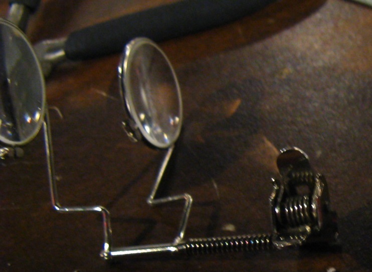
I bent the stems on my loupe so the lenses sit in front of my left eye when it's clamped to the side strap. Enjoyable!

Interlude I: Noam Tries to Lick the Plasma Light Bulb

Interlude II: Nate's Sweet Goggles
Sleepy Nate used brass and rubber plumbing gaskets, set in tan suede. His goggles have a dust mask that can be detached from the right side, to hang out of the way when not in use. (Picture by Noam)

Back to the main feature...
I used a couple of electrical clamps on each side, which not only looks awesome but also provides some adjustability. Attaching these to the strap proved to be the main stumbling block, and the reason why I stalled for a week before finishing them for the Hands-On Museum Local Tech Event last night. (AHA! and 826michigan shared a booth, thanks to sponsorship from Tom Root... more info about our project later.)

The holes in the clamps were too small to push rivets through, and I couldn't find a working drill for many a tiresome day. Once one was located, that and a triangular metal file made the job rather easy (although the rivets barely made it through the whole thickness of leather and metal).

Copper pop rivets installed!

Plate side, minus the loupe (which I do think adds a lot).

I also added some decorative rivets and a mended tear on the right side. Can't have my battle goggles looking shiny-new.

Goggle pics from the Local Tech Event... these were taken with my near-IR webcam and run through Quartz Composer. Further details to come...
Happy happy

I love this picture :D
We were stationed across from Current Motor Co., represented at the event by John Harding, who gave an awesome presentation at Ignite 3 in March. I wandered over and saw the sweet "inverted" motor (ring of magnets on the outside, coils on the inside) that drives their wheels. That's their motorcycle on the left. Mmmm pretty.

Stay tuned for Rotary Ruminations (Sorta) and Robo-Vision!

Tuesday, April 20, 2010

Musical Cyborg Juggling Apparatus


6 1/2 hours in the AHA! Shop and a chocolate-peanut-butter sandwich brought us to this. I'd been stalled out on the method for weeks, and then the clouds suddenly broke, early on April Fool's Day.

So what is this? It is a harness that turns the action of juggling into buzzing noises, flashing LEDs, and arcing electricity. Each palm has two separate copper wires exposed, one of which is hooked up to the positive terminal of a battery, while the other connects to a motor (or bank of LEDs, or people-shocking device). When the wires are bridged by a tinfoil-covered juggling ball, the circuit is closed and the motor (people-shocker, eye-blinder, etc.) runs. Thus, the juggling becomes a method of switching things on and off... like so:
...ish.

And this is what it actually looks like... somewhat less elegant, perhaps. At the top left, we have the left glove with a conductive ball bridging its contacts; below that, a taped-up 12V battery pack (the brown/blue block); then, the box itself. Most of the apparatus is externally mounted. Magnets glued near the four central motors anchor metal bolts, which are struck by the spinning zip ties to create a variety of buzzing sounds (sample mp3!). From the bottom left emerge wires from a shocker, which discharges a decent amount of voltage (I forget how much) across the blue and white wires' stripped ends. It will arc up to about 1cm through the air, which looks pretty sweet, and also give you a pretty hefty shock. (Me holding one contact + Amanda holding the other + proximity -> lightning hands!)

Not pictured: burned-out LED bank... I am not yet wise in the science of adding resistors. But a new, more awesome version is on the way.

The box belts to my waist, and...

suede straps anchor the wires to my arms.

Prototype glove... wire contacts wrapped around a scrap anchor on the inside. Jabby.

Suede glove #1 in production!

Maille rings and thread hold the wires in place. Juggling gloves: now with 50% less pain!


Balls: socks + washers (for heft) + duct tape (for cushioning and adhesive) + tinfoil.

So, there is currently a glove for each hand, plus these:
Finger-contacts! These copper rings are a pain, both figuratively (the donning/doffing process is tedious) and literally (they have a tendency to channel voltage straight through my fingers, resulting in anguish and blisters). But they look... kinda awesome.

I brought this machine to exhibit (with AHA!) at TEDxUofM, which was pretty stupendous. My favorite presenters were John Holland, Udae Sandhu (who voiced basically my current philosophy of happiness), Jacob Mendel's "Zlatá Rybka" video, Mason Proper (!!), Matt Shlian, and Alex Wand (with his awesome marimba-bowing musics). Yesssssss.

AHA! and the Apparatus will also be making an appearance at several future DIY/tech/Maker events, including the Hands-On Museum's Tech Event (May 22), the Ann Arbor Mini Maker Faire (June 5), and hopefully the Detroit Maker Faire (July 31 - August 1). Actually, this post is part of my application for Detroit... I anticipate all three being fantastic.

Friday, March 19, 2010

(Do Breadboards Dream Of) Electric Jam

IT LIVES!


Last Saturday, I finished Make's crackerbox amp project. This is extremely exciting, as it represents a) a successful first foray into the twin lands of circuit diagrams and building electronics from scratch, and b) the actualization of my own electric mandolin!

Janky janky janky. But it works! (I had very limited wire resources... hence, everything is the same color.)

This soldering job reminds me of Kate Beaton's fat pony: ugly and incompetent, but kind of endearing...

While Make seems to have some kind of sponsorship thing with Radio Shack, I don't recommend going there for parts. I moseyed down there one evening, and walked out feeling like I'd lost two hours (including bus time) and spent twice as much as I should've for the components I got. Even if you go online to avoid getting ripped off as much, it could easily cost more than $5 if you don't have most of the stuff already on hand. Still, no complaints - I ended up with this...

:)

The best reference material came from http://www.kpsec.freeuk.com/ . Amazing resource for semi-newcomers to the field of electronic jiggery-pokery. I also highly recommend checking out cairn's comments / linked PCB layout pic on the article page. While it was fun to slowly learn how to read the circuit diagram, at times it got extremely frustrating; I found that layout diagram once I was done, and kinda wished I'd had it all along. (Still, it was gratifying to turn the thing on and have noise come out, when I'd wondered if it would do anything but set the carpet on fire.)

With the piezo mounted! I tried poking/cutting holes in the speaker cone for more distortion, but it doesn't seem to make much of a difference... perhaps because I only have an 8-ohm speaker. It came from the local Kiwanis rummage sale - they have a bunch, and I paid a solitary buck for this one.

This amp exists mainly to give grittiness and edge to the mandolin, and that it does, most noticeably in the upper registers. I chose to use surface-mounted pickups because there's no way I'm taking a drill to the mandolin. So I'm going with a piezo wired to a 1/4" plug, courtesy of the excellent Matt Endahl.

Next step: build a case for it. I settled on some 2-walled plastic with linear cells, which David and I pulled out of the art museum dumpster a while back.

Piezo pickup with plug, duct tape, box cutter, Sharpie, nail sink, amp, plastic.

Cut the plastic into three panels, for optimal stability (that whole 3-legs-don't-wobble thing)... plus mega style points.

Top and bottom covers (the top flaps open); speaker hole cutout.

Duct tape "hammer" + nail sink + needlenose pliers -> easy holes, exactly the right size.

Loud = volume, Angry = gain :)

A lot of people asked about volume vs. gain. As I understand it, the chip already amplifies input sound by a certain amount. The gain feeds from the chip back into it, so that basically controls how much the chip amplifies the signal (sound). (Past a certain level, this creates clipping, which makes it sound gritty.) The volume is between the chip and the speaker ("after" the chip), so it controls how much of this already-amplified signal is put through the speaker.

Left side: on/off toggle, 1/4" jack
Center: volume rheostat, gain potentiometer
Right: speaker
Bottom: PCB, 9V battery

Finished! Here's a short sound sample with the mandolin. There are some images up already on Facebook, as I brought it to Build Night last night at AHA...

Rocking out (as best I am able) at the shop.

We also taped it up to the illustrious Amanda's amazing propane tank steel drum. That thing sounds amazing, though as with the mandolin, only the higher registers worked with the amp's distortion. Apparently, I can switch out one of the capacitors, and it'll pick up more bass... so I guess that's a logical next step with this thing. I already tried hooking up some red LEDs inline with the speaker (so they'd pulse along with the sound), but alas, they were too much of a voltage drain and barely any sound came out.

The last couple of photos are from AHA's Facebook page; I believe they were taken by Josh, one of the proprietors of Digital Ops, our venue. I am inexpressibly happy that this space, the group, and the people in it exist. Dudes are seriously awesome.